Clarification Examples
These are a few short examples of calculations required for clarifier design.
Be sure to run this code prior to trying any examples
Tube Settler Design
Design a tube settler for a laboratory scale clarifier. The vertical section of the clarifier, \(v_{z_{ff}}\), has a net upflow velocity of 3 mm/s. This velocity is maintained in the tube settler, \(v_{\alpha}\). The target capture velocity is 0.2 mm/s. The tube settler diameter is 2.54 cm.
Solve for the length of the tube settler.
The tube settler above the floc hopper needs to be 72 cm long. The tube settler should provide a capture velocity of at least 1 mm/s prior to the floc hopper. Thus there should be 11 cm below the floc hopper.
Determining flow through a diffuser
What is the flow rate of a single diffuser in the bottom of the clarifier? Consider a clarifier that is 6 m long, 1 m wide and 2 m deep, with an upflow velocity of 1 mm/s and a diffuser spacing of 5 cm.
What is this question really asking? This question is asking us to understand that each diffuser “serves” a specific cross-sectional area of the clarifier; all of the diffusers together serve the entire area of the clarifier. So, let’s imagine a single diffuser serving a slice of a clarifier. With this in mind, we can easily solve this using \(Q = \bar vA\). The area, \(A\), is the slice of the clarifier that we are serving. We are told that the tank is 1 m wide, so \(W_{tank} = 1\) m. The length of the slice is dictated by the spacing of the diffusers, \(B_{diff}\), so \(B_{diff} = 5\) cm.
The problem statement includes that \(\bar v_{z_{ff}} = 1\) mm/s. Plugging into our flow equation,
The flow rate of each diffuser is \(50 \frac{mL}{s}\).
Identify Failure Modes from Old Design
Look at a proposed design for the bottom of the clarifier, shown in Fig. 195. This design has an influent manifold at the bottom of the tank. Water flows upwards from the influent manifold. At one end of the influent manifold, there is a drain port. Above the influent manifold, there is a single slot that extends the length of the clarifier. There are no diffusers in this design.
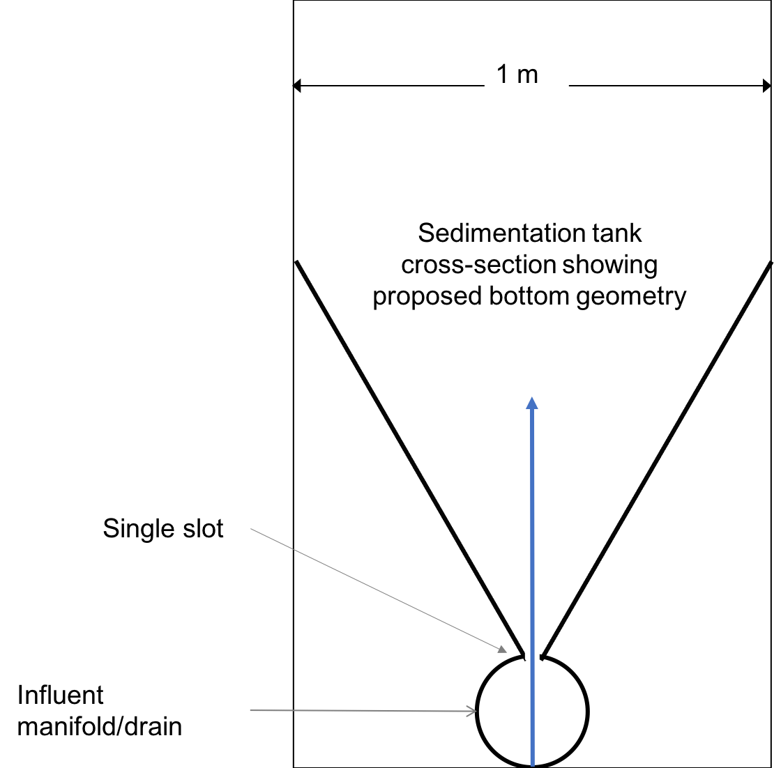
Fig. 195 Proposed clarifier design.
What are the failure modes for this design?
Some issues are:
Flocs can settle in the influent manifold, specifically at the end of the influent manifold pipe
The upflow line jet may be impacted and bent by settling flocs, allowing for floc settling on one side of the tank
Without diffusers, there may not be uniform flow distribution from one end of the clarifier to the other
Without diffusers, there will be large flow circulations inside the clarifier
This design has never been built and never will be. Understanding what the problems are with this design will help us design better in the future.
Diffuser and Jet Reverser Design
Calculate the maximum velocity of water leaving the diffuser based on the maximum head loss. Assume that the majority of head loss is the kinetic energy of the flow exiting the diffuser slot (this assumption will be checked later). Assume K=1.
To find the maximum velocity based on maximum headloss we will use the minor loss equation.
To find the minimum width based on the maximum velocity through the diffuser, we will use conservation of mass. Since it is an incompressible fluid the flow rate entering from the diffuser line jet must be equal to the flow rate up through the clarifier.
Colab worksheet with diffuser design
Answer: The maximum velocity of the clarifier diffusers is 0.4429 meters / second. The minimum width of the clarifier diffusers is 2.409 millimeter.
Calculate the minimum inner width of the diffuser. Assume that the diffuser slot is continuous over the entire length of the clarifier to get an initial estimate (it isn’t actually continuous because it is made from many flattened diffuser pipes).
Diffusers are made by deforming PVC pipe. Softened PVC pipe is forced onto a mold that shapes it into the rectangular shape of the diffuser. (link to clarifier chapter)
What metal plate thickness should be used to make the mold for the diffusers? This value will be the minimum diffuser width. Metal plates are available in 1/16” increments of thickness. The minimum thickness of plate that is strong enough for a mold is 1/16”. The ceil_nearest function defined in utility.py can take in a parameter and an array and it will find the closest value in the array that is at least as big and the parameter. For our problem we will use this to find the plate size that is available and at least as big as the minimum width defined above.
Answer: The width of clarifier diffuser is 0.3175 centimeter
The PVC pipe that forms the diffusers changes in shape and wall thickness during the molding process. The inner width of the rectangle is created by forcing the pipe over a rectangular wedge that is the thickness you calculated above. During the molding process, PVC pipe wall cross-sectional area is conserved. The pipe wall is stretched in total length approximately 20%. Another way to think about this is that the thickness of the wall is reduced by a factor of 1/1.2 because the mass of PVC is conserved and the density is unchanged. Thus, volume and cross-sectional area are conserved.
Area is given using the following Equation \(A_{PVC}=2\left (B_{diffuser}+W_{diffuser} \right)T_{diff}\)
Use the equation for \(A_{PVC}\) to calculate the following:
the outer length of the rectangular diffuser slot, \(B_{diffuser}\).
the inner length of the rectangular diffuser slot, \(W_{diffuser}\).
Answer: The clarifier diffuser outer length: 5.736 centimeter
Clarification diffuser inner length: 5.522 centimeter
Each diffuser serves a certain width and length of the clarifier. Assume that the diffusers are installed so that they touch each other.
4. Determine the flow and velocity through each diffuser. \(Q_{max,diff} = \bar v_{z_{ff}} A\)
\(A = W_{sed} B_{diff}\)
\(\bar v_{diff} = \frac{Q_{max,diff}}{W_{diff} * S_{diff}}\)
Answer: The flow of water leaving a clarifier diffuser is 61.19 milliliter / second The velocity of water leaving the clarifier diffuser is 0.349 meter / second
Recall the formula for Reynold’s number:
\(Re = \frac{\bar v D}{\nu}\) The D is actually just representative of the length scale so we can replace this with the width of the diffuser. \(Re = \frac{\bar v_{diff}*W_{diff}}{\nu}\)
Answer: The Reynolds number for this jet is 974.6 dimensionless
The same principle as above can be applied to this question except the length scale is the width of the clarifier and the velocity is the upwards velocity in the tank.
\(Re = \frac{\bar v_{z_{ff}} W_{sed}}{\nu}\)
Answer: Reynolds number through floc is 938.2 dimensionless. These two Reynold’s numbers are similar because conservation of mass requires for a constant length that \(\bar v_{1}*W_{1} = \bar v_{2}*W_{2}\). The slight difference in the numbers is due to that fact that diffusers are not a continuous line jet but rather broken up by two times the thickness of the pipe wall between the diffusers.
Next, we want to determine the energy dissipation rate for the flow leaving the jet reverser. For this process, you can assume that the jet remains laminar. The flow spreads to fill the gaps created by the walls of the diffuser tubes by the time it traverses the jet reverser. Jet velocity and flow rate are conserved as the jet changes direction in the jet reverser.
7. Calculate the thickness of the jet after it does the 180 degree bend of the jet reverser. < The change in thickness of the jet after the 180 degree bend is due to the flow spreading out to fill in the gaps created by the diffuser pipe walls. \(W_{jet} * \bar v_{diff} = W_{sed} * \bar v_{z_{ff}}\)
Calculate the maximum energy dissipation rate* for the flow leaving the jet reverser. See Equation (75) for the maximum energy dissipation rate in a plane jet and see Table 7 for the value of \(\Pi_{JetPlane}\).
The energy dissipation rate for inlet jet is 158.5 milliwatt / kilogram
In designing AguaClara plants, it is critical to account for all forms of significant head loss. In the clarifier, effluent launders provide about 4 cm of head loss. We want to calculate the exit head loss for water leaving the diffusers to determine whether it is a significant addition to the total head loss through the clarifier.
Calculate the diffuser exit head loss in two ways.
First, calculate the head loss making sure to account for the upflow velocity in the clarifier.
\(h_e = \frac{\left( {{\bar v_{diff}} - {\bar v_{z_{ff}}}} \right)^2}{2g}\)
Second, calculate the head loss but assume that the upflow velocity is negligible.
\(h_e = \frac{\ {\bar v_{diff}}^2}{2g}\)
Answer: The best estimate of the exit head loss for the diffuser is 0.6176 centimeter. The 2nd estimate of the exit head loss for the diffuser ignoring the upflow velocity is 0.6211 centimeter. It is reasonable to neglect the effect of the upflow velocity. The error is 0.005755 dimensionless
Manifolds and Launders
Flow distribution between and within clarifiers is an important design component to ensure good clarifier performance. We need to distribute flow uniformly between clarifiers and also between diffusers on the inlet manifolds.
The following variable definitions and equations will be useful in answering later questions.
Determine the relationship between diffuser exit velocity and the head loss in the parallel paths.
\({h}_{L,ParallelPath}\) is the head loss (flow resistance) in the parallel paths leaving the manifold. The head loss in the parallel path is the total head loss from where the flow leaves the manifold to the point where the parallel flows reunite.
\(\Delta{H}_{Manifold}\) is the variability in piezometric head in the manifold that is driving the flow through the parallel paths.
The ratio of minimum (first diffuser port) to maximum (last diffuser port) flow is given by:
The change in piezometric head is given by: \(\Delta{H}_{Manifold} = \frac{{v_{manifold}}^{2}}{2g}\)
The maximum allowable velocity in the manifold is given by:
Now, we want to find the maximum velocity for an inlet manifold which is dependent on the given flow distribution constraint, \(\Pi_{DiffuserFlow}\), and the head loss in the parallel paths, \(h_{L,ParallelPath}\).
Determine an equation for maximum velocity for an inlet manifold in terms of diffuser exit velocity and the flow distribution constraint.
Write a function for maximum velocity for an inlet manifold using the equations you just found.
Exit losses from the diffusers dominate the head loss because the velocity in the diffuser slots is much higher than the velocity at the entrance to the diffuser pipes. Using the insight from the previous problem, it is reasonable to neglect the effect of the upflow velocity when calculating the exit head loss for the manifold diffusers.
Head loss in the clarifier is impacted by multiple forms of head loss, inlcuding head loss through the effluent launder and diffusers. Head loss through the effluent launder is about 4 cm. You found head loss through the diffusers in Problem 9.
Which form of head loss (effluent launder or diffuser) is in the parallel path, \({h}_{L,ParallelPath}\)? What is the maximum velocity in the clarifier manifold?
Answer: Only the diffuser head loss is in the parallel paths. The maximum velocity in the clarifier manifold is 0.2313 meter / second.
The ratio of manifold pipe cross-sectional area to total diffuser cross-sectional area determines the flow distribution between diffusers.
Calculate the ratio of manifold pipe cross-sectional area to total diffuser cross-sectional area. You can use the velocities of the manifold and the diffusers to calculate the areas.
Since the clarifier has a constant volume, the flow rate into the tank is equal to the flow rate out of the tank: \(Q_{manifold,pipe} = Q_{diff}\)
\(v_{manifold} * A_{manifold} = v{diff} * A_{diff}\)
\(\frac{A_{manifold}}{A_{diff}} = \frac{v_{diff}}{v_{manifold}}\)
What is the significance of the flow area ratio that you found? What does it tell you about the relative areas?
Answer: The flow area ratio of manifold pipe to diffusers is 1.509 dimensionless. This means that the manifold flow area is larger than the total diffuser area. The flow distribution is more uniform because the diffuser velocity is higher than the manifold velocity.
The maximum clarifier flow rate is currently set by the constraint of using a single length of pipe for the manifold and launder. The maximum length of the upflow region of the clarifier is 5.8 m, as given below.
What is the corresponding clarifier flow rate? This can be solved using \(Q = \bar v A\).
Answer: The maximum flow rate in one clarifier is 6.187 liter / second.
The maximum clarifier flow rate dictates the required pipe diameter for the manifold and launder.
7. What is the minimum inner diameter of the clarifier manifold? \(Q = \frac{\bar v*\pi*D^2}{4}\)
8. What is the required nominal pipe diameter given this flow rate? The function from the pipe database can return the nominal diameter from the diameter and SDR.
Answer: The minimum inner diameter of the clarifier manifold is 7.266 inch. The nominal diameter of the clarifier manifold is 8 inch.
Clarifier Bays and Number of Diffusers
The design will be for a 60 liter per second plant.
Answer: The plant view area of the floc filter is 60 square meters.
Answer: The total length of the floc filter zone for all tanks is 56.24 meters.
How many clarifiers are required to treat the total plant flow? The plant flow rate is the basis of design and the maximum clarifier flow rate is based on the manifold diameter.
Answer: The required number of clarifiers is 10.
Answer: The total amount of water this plant could treat is 61.87 liter / second. It is slightly larger than the basis of design due to the needs for an integer number of clarifiers.
How many diffusers are required in each tank? Assume the maximum length of the upflow region of the clarifier is used.
Answer: The number of diffuser pipes per clarifier is 98.
Plate Settler Design
We will assume that the active area of the clarifier is equal to the top area of the floc filter zone. This isn’t quite right because of the geometric constraints from the floc hopper, inlet channel, settled water channel, and angled plates. However, it is a good approximation for these long tanks.
The equation for this problem can be found in Clarification Derivations.
Answer: The minimum length of the plate settlers is 0.4619 meters.
The equation for this problem can be found in Clarification Derivations.
Answer: The horizontal center to center spacing of the plate settlers is 3.118 centimeter.
Approximately how many plate settlers spaces are needed in each clarifier? Assume the maximum length of the upflow region of the clarifier is used. Neglect the lost space at the end of the clarifier due to the angle of the plate settlers.
Answer: The number of plate settlers per clarifier is 180.
Comments, Corrections, or Questions
This textbook is an ever-evolving project. If you find any errors while you are reading, or if you find something unclear, please let the authors know. Write your comment in this Github issue and it will be addressed as soon as possible. Please look at other comments before writing your own to avoid duplicate comments.