Rapid Mix Design
As of 2018 the design for AguaClara rapid mix units has been based on the goal of achieving a target energy dissipation rate. This in turn was based on the assumption that it was important to rapidly mix the coagulant with the water, perhaps to minimize the self-aggregation of coagulant nanoparticles. We don’t yet have any experimental evidence that rapid mixing is important and it is quite likely that the energy dissipation rate found in the hydraulic flocculator is sufficient to provide the required mixing.
The design requirements for fluid mixing of the coagulant is an area that needs research. If the goal is to reduce the amount of self-aggregation of coagulant nanoparticles, then it is possible that an investment in energy to mix faster could be offset by a reduction in the chemical demand. This tradeoff needs a full economic and resource-use analysis. Regardless of the outcome of that analysis, it is essential that we evaluate options to reduce the energy input required to reduce the mixing time. One excellent option for reducing the energy required is to reduce the length scale of the largest eddies that are required for mixing.
The mixing time is dominated by the turnover time of the largest eddies. Given an energy dissipation rate (or a velocity gradient) the mixing time is reduced if the required length scale of the mixing is reduced.
We will design a rapid mix unit that has an array of injection ports and couple that with flow expansions that will generate eddies at that same length scale. The reason for creating flow contractions at the same length scale as the distance between injection ports is to immediately create eddies of the right size rather than creating much larger eddies and then waiting for the turbulence cascade of eddies sizes to create the smaller eddies. By creating eddies with dimensions similar to the injection port separation we will dissipate the energy as quickly as possible (at that smaller length scale) and thus decrease the mixing time.
We can use the center to center distance of the contractions (and injection ports) as the eddy length scale. This is because the eddies will need to mix over the length scale of the spacing of the injection ports.
The relationship between head loss and energy dissipation rate is based on conservation of energy with \(\theta\) representing the time required for most of the energy to be dissipated.
We will assume that the time for the energy to dissipate, \(\theta\), is \(t_{eddy}\). Eliminate the unknown \(\bar\varepsilon\).
where \(t_{eddy}\) is the mixing time and \(h_e\) is the head loss that will be used to obtain the mixing. Solve for \(L_{eddy}\) which is the spacing of the contractions and the spacing of the coagulant injection points.
The raw water flow rate per injection port is equal to the water velocity upstream from the contractions in the channel or pipe multipled by the area of flow dedicated to one injection port.
Substituting the previous equation for the eddy length scale, \(L_{eddy}\), we obtain
The flow rate that can be served with a single injection port is a function of how much energy we use for the mixing process. Colab worksheet calculating the flow rate that can be served with a single injection port
The flow rate per mixing zone increases rapidly as the mixing time allowed is increased and as the energy input is increased.
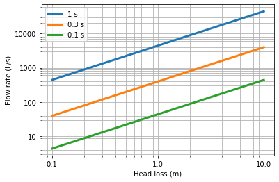
Fig. 84 The flow per mixing zone increases with the amount of energy used. The amount of energy used can be decreased by a factor of 100 if multiple injection ports are used.
The rapid mix unit will be created by placing round cylinders vertically in the inlet channel or pipe. The goal is to minimize the number of chemical injection points and thus to use as large a spacing of the cylinders, \(L_{eddy}\), as possible.
The dimensions of the opening between cylinders and the diameter of the cylinders can be obtained by analyzing the head loss through a flow expansion.
Where con = contracted control surface and exp = expanded control surface. We can solve the head loss equation for the dimensions of the contractions. First, solve for the area ratio
Here the area ratio is also equal to the width ratio because the depth of flow is the other dimension. We assume here that the depth of flow is large compared with the head loss.
The width of the expanded flow, \(W_{exp}\), is equal to the large eddy length scale, \(L_{eddy}\).
The diameter of the cylinders is equal to
Colab worksheet designing rapid mix unit is an example design for a rapid mix unit that uses 20 cm of head loss and achieves mixing in 0.3 seconds.
The spacing between injection ports is 0.4201 meter
The flow rate of raw water per chemical injection point is 79.43 liter / second
The number of injection ports is 36.0
The expansion ratio is 5.401 dimensionless
The width of the contractions is 0.07779 meter
The diameter of the cylinder is 0.3424 meter