Clarification Introduction
The floc interactions in the clarifier include four processes.
Floc filter: fluidized suspension of flocs that filter out smaller particles
Plate settler particle capture: capture small flocs that settle slower than the upflow velocity in the floc filter
Plate settler aggregation: small flocs aggregate into large flocs as they slide down the plate settler incline
Floc hopper consolidation: excess flocs flow into the floc hopper where they consolidate before being wasted
Symbol |
Description |
Terminal velocity |
|---|---|---|
|
Flocs and raw water particles that settle too slowly to be captured by the plate settlers |
\(v_t < v_c\) |
|
Flocculator flocs that settle fast enough to be captured by the plate settlers |
\(\bar v_{z_{ff}} > v_t > v_c\) |
|
Floc filters that form as |
\(v_t > \bar v_{z_{ff}}\) |
|
Floc filters that no longer have capacity to capture |
\(v_t > \bar v_{z_{ff}}\) |
The video linked to Fig. 139 provides the context for the following description of the processes.
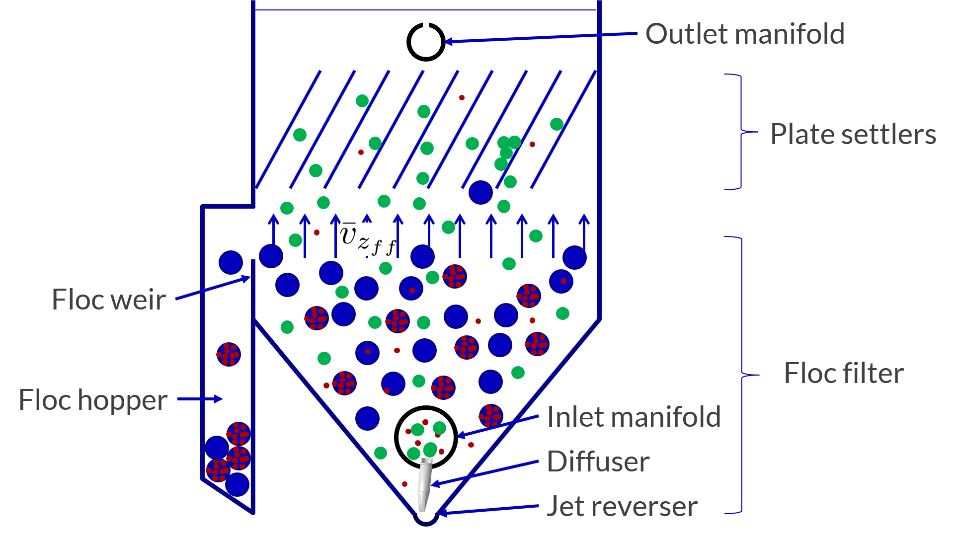
Fig. 139 AguaClara clarifier showing the four types of flocs and animation (click for video).
The inlet manifold supplies  that settle too slowly to be captured by the plate settlers and
  that will be captured by the plate settlers. Before the floc filter forms the are not removed by the clarifier and exit through the outlet manifold.
The settle on the plate settlers and then eventually slide down the plates in an avalanche (see animation of floc aggregation on a plate settler). As the flocs slide down they aggregate into  . The conversion of into provides the mechanism for the flocs that are captured on the plate settlers to increase their terminal velocity so that they can fall back into the bottom of the clarifier. If didn’t convert into there wouldn’t be any way for flocs captured by the plate settlers to exit from the bottom of the plate settlers.
The have a fractal dimension of approximately 2 and thus are very porous. A significant amount of water flows right through these porous flocs (Fig. 140 and animation of floc capture). As water flows through the floc some of the collide with similar sized particles that are held in place inside the floc.
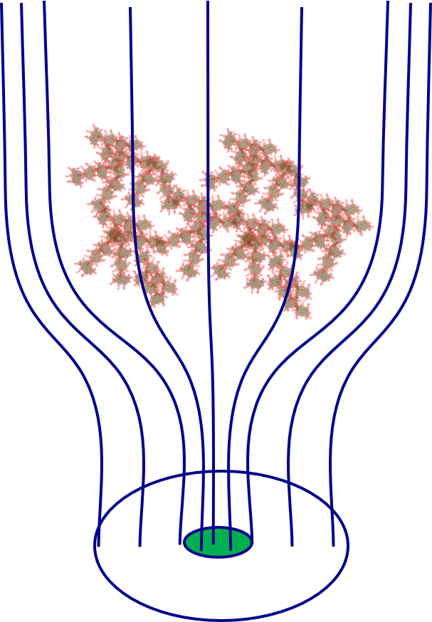
Fig. 140 Streamlines go around and through a floc filter. The fraction of the flow that goes through the floc is a function of the floc porosity.
As the floc filters, , capture the particles that otherwise would have escaped the clarifier, , the porosity of the decreases and less flow goes through the floc. Eventually the floc becomes loaded to capacity with and the resulting  is no longer able to capture any more .
Mass conservation requires that at steady state the mass flux of solids into the clarifier match the flux of solids out of the clarifier. If the clarifier is functioning as designed and the coagulant dose is correct the majority of the incoming solids will be converted into large flocs ( and ) and those flocs will flow over the top of the floc weir.
Inlet and Floc Resuspension
Delivering the flocculated water to the clarifier is one of the most critical design steps for ensuring successful operation of a water treatment plant. Design failures commonly produced much higher turbidity in the clarifier effluent due to large scale circulation that is set up in the clarifier basin due to the momentum of the incoming flow. The AguaClara design has evolved to eliminate large scale circulation and to ensure that the flow is distributed equally to all of the clarifier bays.
Water enters the clarifier bay through the influent manifold. Water exits the influent manifold through a series diffusers in the bottom of the pipe shown in Fig. 141. Diffusers are what we call short stubs of pipe that extend perpendicular to the influent manifold. The diffusers point down to the bottom of the clarifier bay and extend along the length of the influent manifold at regular intervals to ensure that water is evenly distributed within the bay. The ends of the diffuser tubes are flattened so that they are thin rectangles and when placed side-by-side achieve a line-jet effect. The end of the influent manifold is capped.
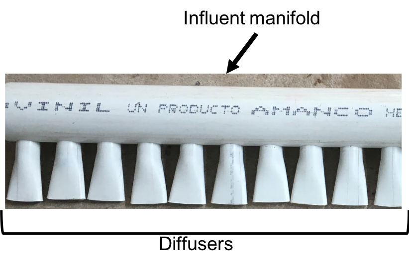
Fig. 141 Influent manifold with diffusers.
The influent manifold diffuser system straightens the fluid jets that are exiting the manifold so that they have no horizontal velocity component as shown in Fig. 143. This is critical because even a small horizontal velocity causes a large scale circulation that transports flocs directly to the top of the clarifier as shown in Fig. 142. Influent manifolds without flow straightening diffusers are commonly used in vertical flow clarifiers including designs by leading manufacturers.
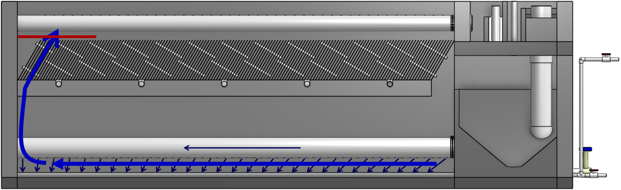
Fig. 142 Flow with a horizontal velocity component that causes problematic flow circulation.
The horizontal flow created by the direction of flow inside the manifold results in preferential flow through the plate settlers at the terminal end of the manifold. This is a common problem in conventional clarifiers that don’t have flow straightening diffusers or that have horizontal flow in the tank.
The underlying cause of the poor flow distribution between plate settlers (shown in Fig. 142) is because the head loss through the plate settlers is inconsequential and thus there can’t be any significant horizontal velocity below the plate settlers. It is possible that some plate settler manufactures address this issue by adding flow control orifices at the top of the plate settlers that add sufficient head loss to the flow through every plate settler to minimize the impact of velocity differences below the plates.
The AguaClara solution is to use flow diffusers that simultaneously eliminate horizontal flow and create a line jet that resuspends settled flocs to maintain the floc filter in suspension.
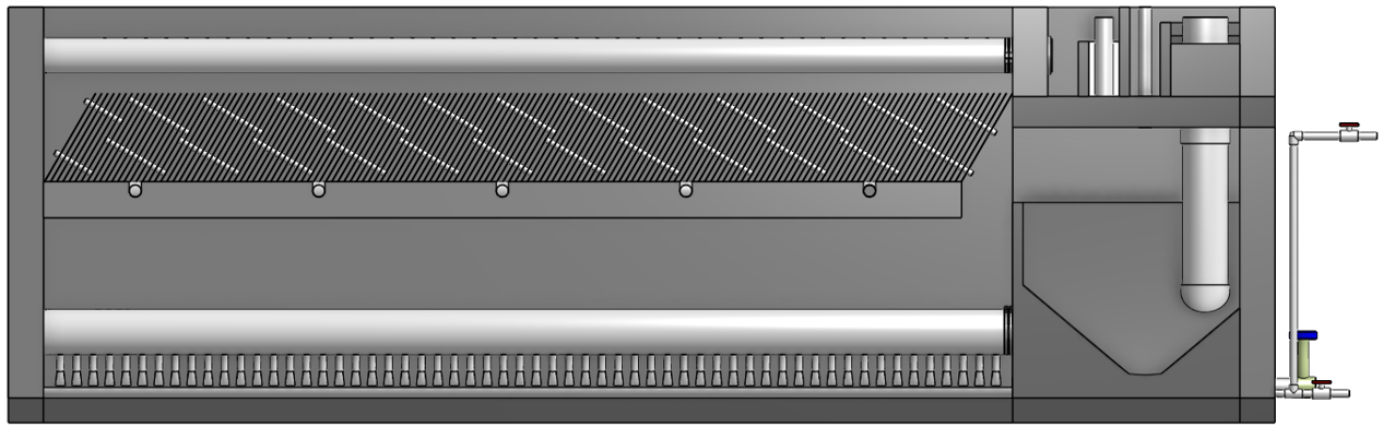
Fig. 143 Flow with the diffusers to remove horizontal velocity component to prevent problematic flow circulation.
The diffusers create a line jet that spans the entire length of the clarifier. This line jet enters the bay going down, but we want the water to ultimately flow up to make our vertical flow clarifier. To get the flow to redirect upwards, we use a jet reverser, which is half of a pipe that is laid in the bottom of the bay.
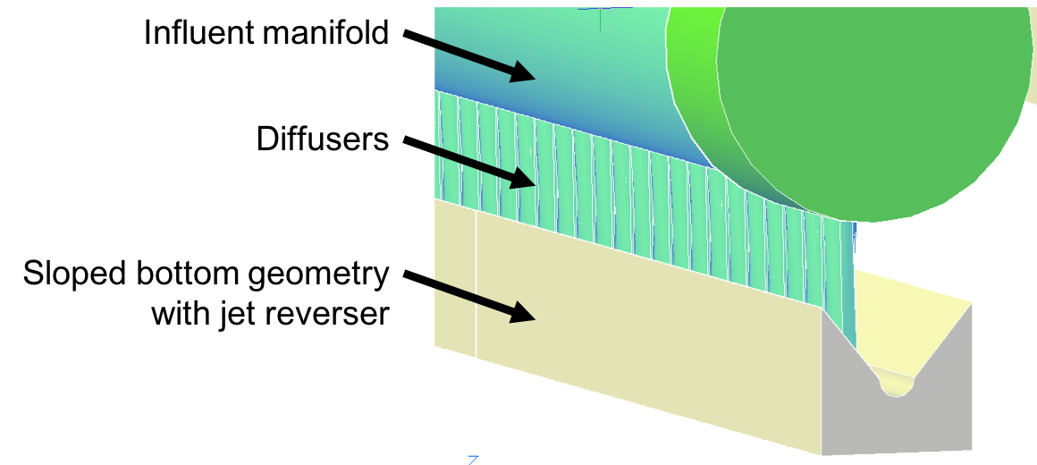
Fig. 144 Cross-section of the bottom of the clarifier.
You may be wondering, why do we need a jet reverser in the first place? Why don’t we just have the diffusers point up to avoid having to change the flow in the first place? The answer has multiple components.
If the diffusers were to point up, that would mean that any sedimentation that happens near the terminal end of the manifold would accumulate and the sediment would have no way of being removed.
If flow were just to point directly up, it would not have an opportunity to sufficiently spread into the width of the clarifier bay, which could lead to “short-circuiting” and poor flow distribution overall.
The jet reverser functions as a way to keep flocs suspended by ensuring that anything that settles will be propelled back up from the force of the diffuser jet. The jet reverser and diffuser alignment is not symmetrical; the diffusers are directed to one side of the jet reverser (either by slight rotation of the inlet manifold or by an offset). This is intentionally done to ensure that the diffuser jet never collapses to promote a floc filter, which will be discussed next. Fig. 145 shows that flat bottomed and centered jets do not create a floc filter while offset jets are stable.
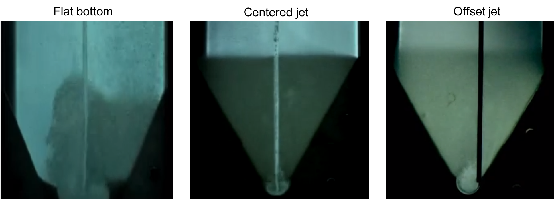
Fig. 145 The jet reverser and diffuser alignments; the offset jet is the most successful.
There is a lot of research interest in determining the optimal upflow velocity for floc filters considering that high velocity is better for resuspension but breaks more flocs. Currently, AguaClara plants use an upflow velocity of 1 mm/s.
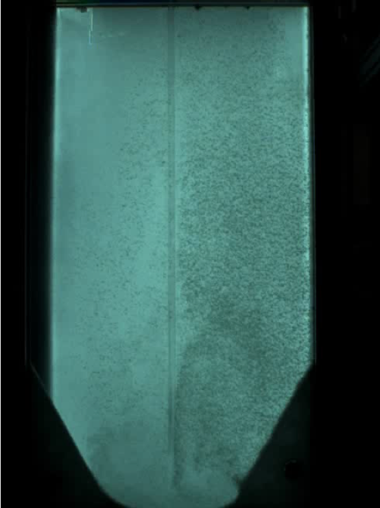
Fig. 146 Flat bottomed tank with settled flocs (click to be sent to video).
As shown in Fig. 146 and the linked video, in a flat bottom geometry, flocs settle in the corners of the tank because there is no direct flow of water to resuspend it. Flocs fall in such a way that the corners of the tank will fill first, with more and more flocs settling until the angle of repose is created. This angle that is occupied by flocs suggests that if we want to avoid having flocs settle, we should fill the sides of the tank in with concrete and create a sloped bottom so that there are no surfaces for settling.
Successful floc filter formation is shown in Fig. 147. Studies by AguaClara researchers have found that floc filters improve the performance of a clarifier and reduce settled water turbidity by a factor of 10 for multiple reasons (Garland et al., 2017).
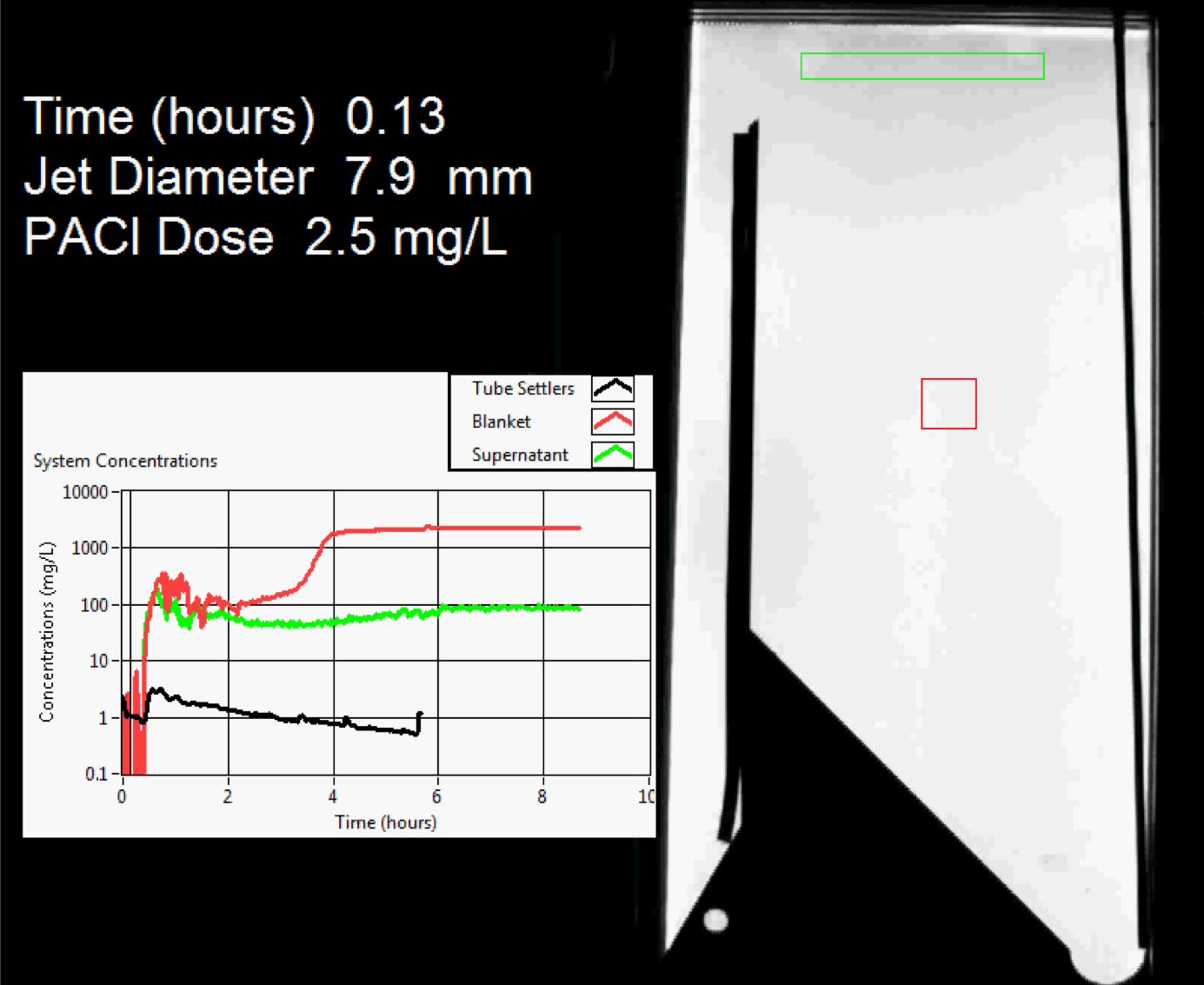
Fig. 147 Floc filter formation over time (click to be sent to video).
The influent manifold, diffusers, and jet reverser work with a sloped bottom geometry in an AguaClara plant. The slope on either side of the diffusers is at a 50 degree angle. The bottom geometry allows for smooth flow expansion to the entire plan view area of the bay, and ensures that all flocs that settle are transported to the jet reverser. The diffusers do not touch the bottom of the tank so that flocs on both sides of the diffuser can fall into the jet reverser for resuspension. Thus, there is no accumulation of settled flocs in the clarifier bays. Sludge that is allowed to accumulate in the bottom of clarifiers in tropical and temperate climates decomposes anaerobically and generates methane. The methane forms gas bubbles that carry suspended solids to the top of the clarifier and cause a reduction in particle removal efficiency. The AguaClara clarifier bottom geometry prevents sludge accumulation while also ensuring good flow distribution.
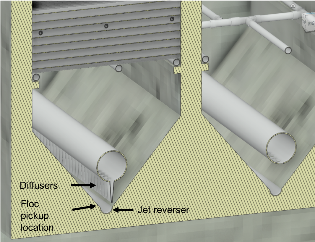
Fig. 148 Cross-section of the bottom of the clarifier.
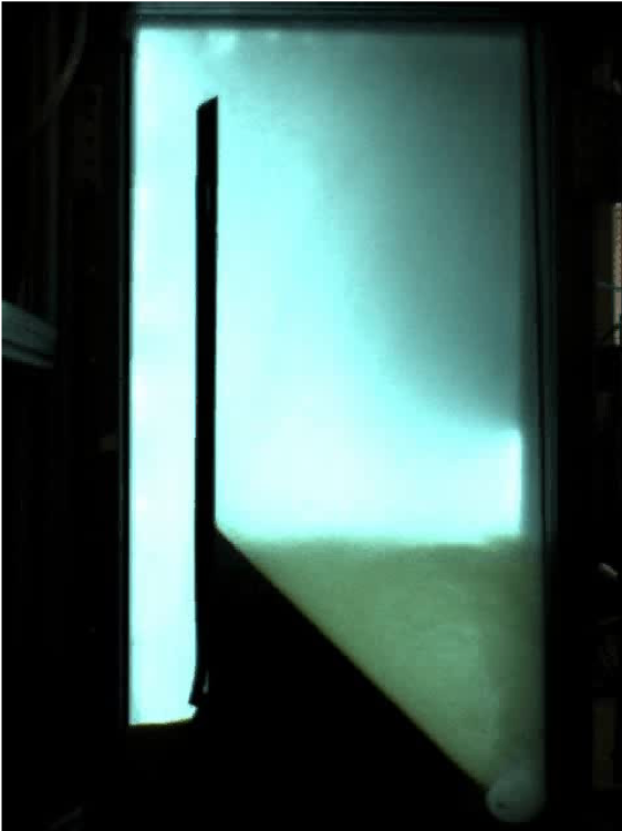
Fig. 149 Sloped bottom tank with fully suspended flocs (click to be sent to video).
So we know that the diffusers, jet reverser, and sloped bottom ensure that no sludge accumulates in the bay by creating a system to resuspend any settled flocs.
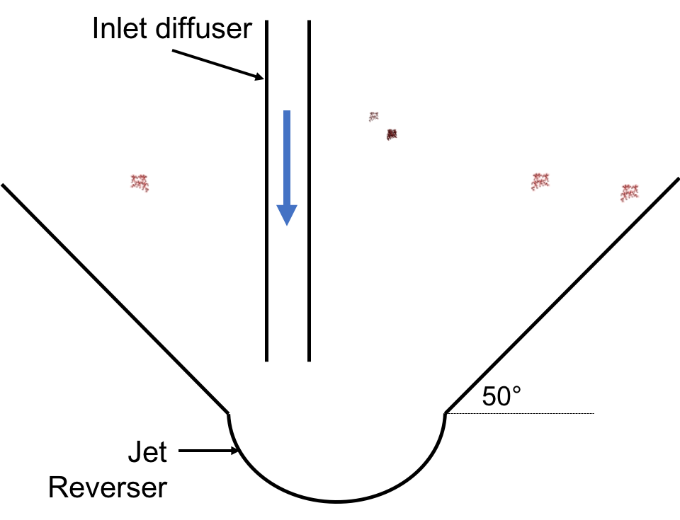
Fig. 150 Distribution of flocculated water and resuspension of settling flocs (click to be sent to video).
What are the failure modes for this system? For one, we need to ensure that the jet of water exiting the diffuser is able to maintain its upward direction after the jet reverser. The jet is influenced by the flows that are coming down the sloped sides of the tank. Thus, the jet must have enough momentum to remain upwards even with the momentum from other flows downwards. We can control the momentum of the jet by controlling the cross-sectional area of the diffuser slot. A smaller cross-sectional area will increase the velocity of the jet but the mass is the same because the flow rate for the plant is the same, thus increasing the momentum.
Garland, 2016 showed that the jet was unable to resuspend the flocs when the jet velocity was 57 mm/s and was successful for all velocities greater than 75 mm/s. The momentum of the floc density current will increase with the concentration of flocs in the primary filter which is in turn a function of the density and size of the core particles. The primary filter floc concentration will decrease at lower temperatures and thus failure of the jet reverser will occur at high temperatures. Given that Dr. Garland did the research at room temperature using a kaolin suspension it is likely that the 75 mm/s guidelines is sufficiently conservative for all designs that have a 1 mm/s upflow velocity. The jet reverser will fail at some point as the flow rate through the clarifier is decreased. The solution for that case would be to take a fraction of the clarifiers off line to maintain a higher jet velocity.
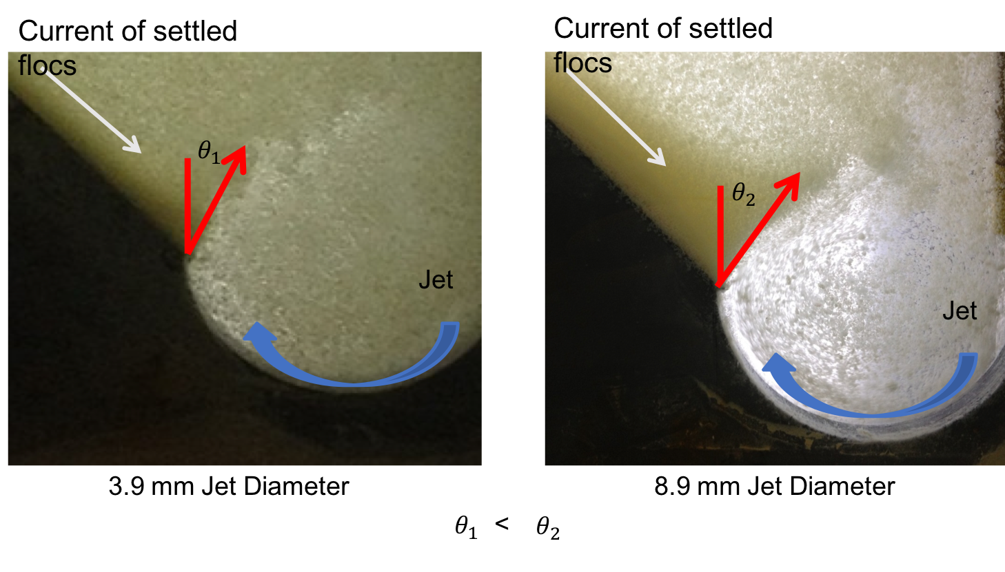
Fig. 151 Jet diameter and current of settled flocs.
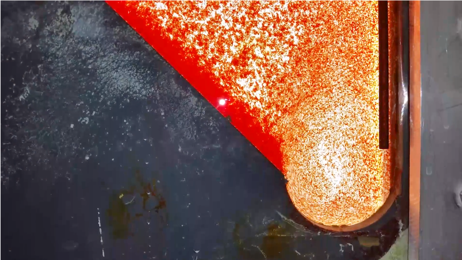
Fig. 152 Jet reverser resuspending flocs (click to be sent to video).
Diffuser Fabrication
Diffusers are shaped so that one end is a circular pipe that fits into the influent manifold orifice, and the other end is deformed to the shape of a thin rectangle, as shown in Fig. 153.
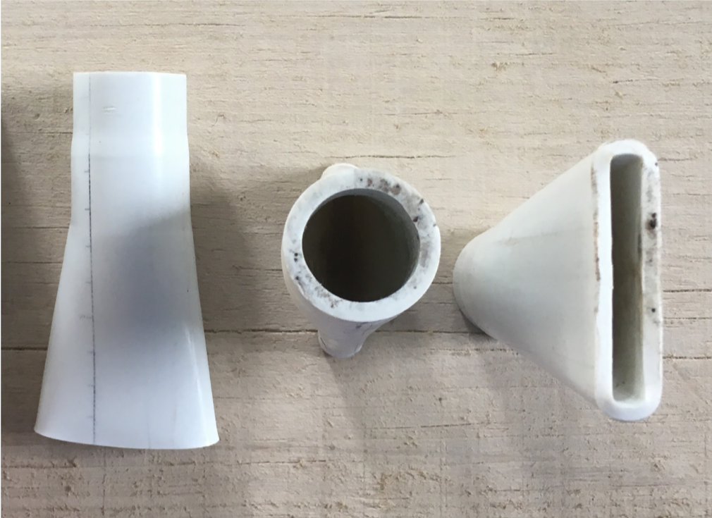
Fig. 153 Side, top, and bottom view of a diffuser.
Recall that this deformation is done to create a line jet entering the jet reverser in the bottom of the clarifier. Diffusers are shaped by dipping the pipe stubs in hot oil, and then pushing the maleable and heated pipe onto a metal form, as shown in Fig. 154. This metal form is sized so that the target shape is achieved.
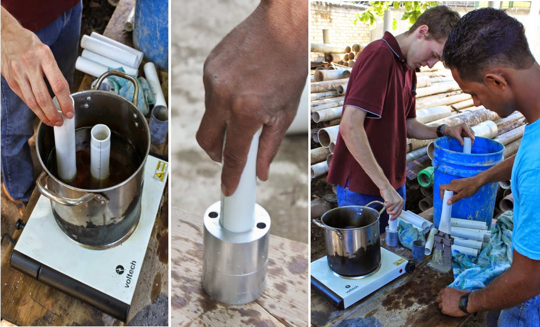
Fig. 154 Process of heating the PVC in oil and molding the diffuser shape on the metal forms.
Sedimentation and Plate Settlers
Sedimentation is a gravity-driven unit process in which suspended flocs are settled out from water. Large flocs made up of many primary particles and coagulant will settle if given enough time. Clarification is commonly preceded by flocculation to form flocs which will be large enough to settle in the clarifier - and is commonly followed by filtration to capture particles that passed through the clarifier. Sludge consolidation processes are often present alongside clarifiers to reduce the waste stream of settled flocs. Optimizing clarification is important because the more particles that clarifiers can remove, the fewer particles the filter will have to remove. This is good because filters can only handle a small amount of solids, and cleaning the filters with backwash uses a lot of water so we want to reduce the number of backwashes.
To introduce you to sedimentation, we will begin with a simple example. If a jar of water filled with flocs was left at rest, flocs would begin to settle due to gravitational forces pulling them down. Large flocs would settle first, but if left for long enough, all flocs would settle to the bottom of the jar. In its most basic form, the jar represents a clarifier in which flocculated water is treated. Settled flocs are waste and the water on the top of the jar, referred to as the supernatant, is the clarified water.
Constraints of space, time, and cost make it important to optimize the settling process. It would not be realistic to design water treatment systems that use the basic jar-like system to settle flocs because large flow rates would require unreasonably large reactor volumes and long retention times. The goal of clarifier design is to employ geometries that promote settling and allow for fast treatment with small footprints.
What if we were to do the same jar experiment with raw water that did not go through successful coagulation and flocculation? Would we observe the same settling and successful particle removal? To answer this, we must recall information learned in the section on coagulation and flocculation; those two treatment processes serve to destabilize and agglomerate particles to form flocs that will be heavy enough to settle. If the particles are colloids and are not destabilized, no amount of time will allow for the settling. This emphasizes the fact that successful clarification can only happen after successful flocculation.
The three main steps that need to be accomplished for a clarifier to be successful are as follows:
Small flocs need to be able to settle to a plate or tube settler surface.
Settling flocs in the floc filter need to be able to move from wherever they settle to a resuspension zone.
Excess flocs must be removed from the floc filter and allowed to consolidate before being wasted.
Clarification is ubiquitous in water treatment. Nevertheless, the process is very complex with many failure modes and there are many active research areas. The following sections will explore the state of conventional sedimentation systems and their challenges, gaps in knowledge, and the AguaClara approach to clarification.
To understand how clarification works, a few key concepts must first be developed. This includes understanding how and why flocs move in water. Remember, one of the goals of clarifiers is to optimize the floc-settling process.
Terminal Velocity and Capture Velocity
Sedimentation is the process of particles ‘falling’ because they have a higher density then the water, and its governing equation is (1). The terminal velocities of particles in surface waters range over many orders of magnitude especially if you consider that mountain streams can carry large rocks. But removing rocks from water is easily accomplished, gravity will take care of it for us. Gravity is such a great force for separation of particles from water that we would like to use it to remove small particles too. Unfortunately, gravity becomes rather ineffective at separating pathogens and small inorganic particles such as clay. The terminal velocities (Equation (1)) of these particles is given in Fig. 155.
Colab worksheet plotting the terminal velocity
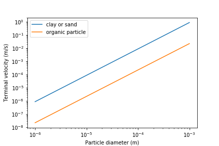
Fig. 155 The terminal velocity of a 1 \(\mu m\) bacteria cell is approximately 20 nanometers per second. The terminal velocity of a 5 \(\mu m\) clay particles is 30 \(\mu m/s\). The velocity estimates for the faster settling particles may be too slow because those particles are transitioning to turbulent flow.
The low terminal velocities of particles that we need to remove from surface waters reveals that sedimentation alone will not work. The time required for a small particle to settle even a few mm would require excessively large clarifiers. This is why flocculation, the process of sticking particles together so that they can attain higher terminal velocities, is perhaps the most important unit process in surface water treatment plants.
Capture velocity is defined as the velocity of the slowest settling particle that a clarifier captures reliably. It is a property of the geometry of the clarifier. Because it is a property of geometry, we can use it as an important design tool; because we can control reactor geometry, we can control the sizes of particles that we can settle. However, the size of particles that a clarifier can capture is also a function of the viscosity of the water and thus is influenced by temperature.
Note that there are a couple of different terms used to describe the sedimentation process. We can say that clarifiers “capture” particles when particles settled. We can also say that clarifiers “remove” particles. Both terms refer to the process of particles or floc settling out of suspension in water. Clarification tanks separate some particles from the water and eventually divert those captured particles into a waste stream.
We will develop our definition of settle capture velocity using examples of horizontal flow and vertical flow clarifiers. It should be noted that there are many idealizations and simplifications made for modeling clarifiers. We assume that water will move through the reactor as expected (in the case of the horizontal flow clarifier, from one end to the other), but we know that there are many more fluids complications than are described here. We assume that everything is moving at the average velocity and there are no turbulence or velocity profiles. For the time being, we will ignore what will happen to particles once they are captured by the clarifier. Our intuition tells us that particles which settle will need to be removed somehow, and that is correct. For now, we only care about capturing the particles, and later we will care about what we do with them once they are captured.
Temperature plays an important role in sedimentation processes. Colder temperatures mean more viscous fluid; particles suspended in viscous fluid don’t fall as quickly as they would in warmer, less viscous fluid. Clarification tanks don’t work as well in cold temperatures as they do in warm temperatures. If the goal is for the clarifier to remove a certain size of particle, then the required capture velocity must also be a function of temperature. Keep this in mind throughout the chapter as you learn how capture velocity drives to plant design.
Horizontal Flow Clarifier

Fig. 156 Horizontal flow clarifier.
Let’s begin with a few questions that will describe our horizontal flow clarifier in Fig. 156. We will assume that 1) water travels uniformly from one end of the tank to the other, and 2) the particle that we are discussing is 35 \(\mu m\) (which is the size of particle that AguaClara plate settlers can capture).
1) How much time is required for water to pass through the tank?
To determine this value, we can use the given volume and flow rate information by the following relationship:
2) In the “worst case scenario”, how far must a particle fall to reach the bottom of the tank?
The “worst case scenario” is the condition in which a particle must travel the furthest in order to be successfully captured by the clarifier. We assume that particles are evenly distributed throughout the height and width of the reactor entrance. Therefore, a particle entering at the top of the entrance of the reactor would need to fall a distance of \(H\) to reach the bottom. Any particle entering from a position lower than the top of the tank would need to fall a distance \(< H\). We refer to the “worst case scenario” pathway as the “critical path” of the particle in the clarifier design because this is the case which we must design to treat. The height that the particle must fall is called the “critical height”, \(H_c\).
3) How fast must the particle fall?
We know that for a particle to fall to the bottom successfully, it needs to fall fast enough that it can reach the bottom before the water that is carrying it leaves the reactor. Water is carrying the particle across the reactor at the horizontal velocity speed, \(v_H\). Gravity is causing the particle to settle at its terminal velocity, \(v_t\). In order to reach the bottom, that settling velocity needs to be the capture velocity, \(\bar v_c\), to ensure that the particle will reach the bottom of the reactor. We can see the critical path of the particle in Fig. 157.

Fig. 157 Horizontal flow clarifier with capture velocity.
Capture velocity can be determined by the distance that a particle must travel and the time that the particle has to travel.
We can make some substitutions into the equation for \(\bar v_c\) to solve for it in explicit terms of reactor plan view area. We are interested in plan view area because this will indicate the efficiency and cost of an associated reactor.
Thus, we have capture velocity which is a descriptor of a clarifier. It determines how fast a particle has to settle in order to be reliably captured by a particular clarifier, assuming idealized flow. The capture velocity is not a particle property, but rather a clarifier property.
4) Will any particles that are smaller than 35 \(\mu m\) be captured in the clarifier?
This question is important because as stated in the beginning of this section, our discussion assumed that the particle in question was 35 \(\mu m\). If we design a clarifier to capture particles that are 35 \(\mu m\), we also have to understand the impact of our design on particles smaller than 35 \(\mu m\).
To answer this question, think about the two extremes of our reactor.
We could have a small particle entering the reactor at the top, defining the critical path in the same “worst case scenario”. This particle would not be successfully captured by the tank because its terminal velocity is less than the capture velocity, meaning that it doesn’t have enough time in the reactor to settle.
We could have a small particle entering the reactor near the bottom, in a “best case scenario”. In this case, the particle does not have a large distance to fall because it is already close to the bottom of the tank. Small particles entering the reactor may be able to be captured by a tank designed for particles 35 \(\mu m\) or larger, but it depends on the height at which they enter the reactor as shown in Fig. 158.
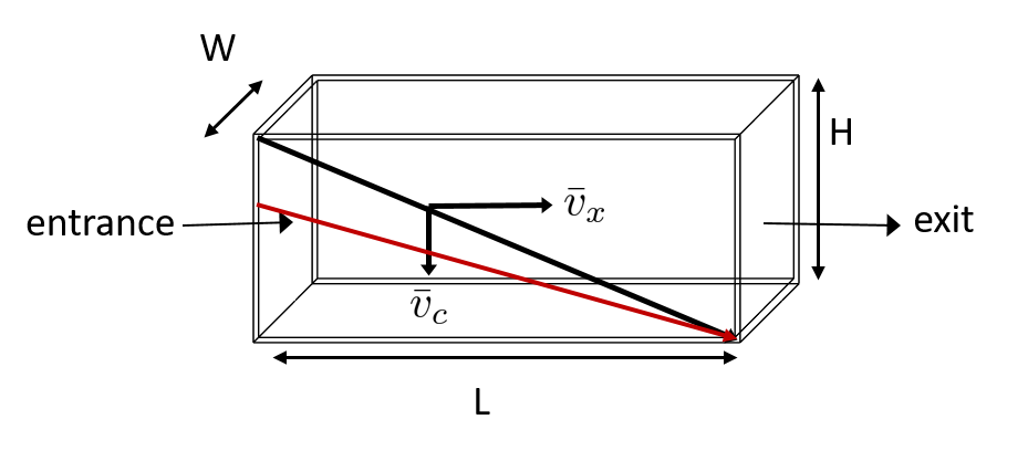
Fig. 158 Horizontal flow clarifier with critical path and small particle.
Vertical Flow Clarifier
We will complete the same exercise for vertical flow clarifiers shown in Fig. 159. In vertical flow clarifiers, water flows up from the bottom of the reactor and exits near the top of the reactor.

Fig. 159 Vertical flow clarifier.
1) How much time is required for water to pass through the tank?
The answer is the same for the horizontal flow clarifier because this is a property of reactor flow rate and volume.
2) How far must a particle fall relative to the fluid to not be carried out the exit?
Note how this question is different from the question we asked for the horizontal flow clarifier. In the horizontal flow clarifier, particles could settle to the bottom of the reactor. We care about particles settling to the bottom because we assume that if particles hit the bottom of the reactor, then they would be captured and would not leave the reactor. Remember, the goal of sedimentation is to remove particles from suspension in water. In the vertical flow clarifier, we also want to remove particles from suspension, but because there is a different geometry, we are now interested in the relative movement of particle to water. If a particle is falling due to the forces of gravity, but also water is pushing up on it, the only way for a particle to remain in the reactor is if it either falls at the same velocity or faster than the water is pushing it.
If a particle is falling at the same velocity that water is moving it, it will be stationary in the reactor. Water flowing through the reactor moves a distance \(H\) in time \(\theta\), which means that a stationary particle must settle the same distance \(H\) in the same time \(\theta\). Therefore, the answer is \(H\).
3) How fast must the particle fall (relative to the fluid)?
We determined in the previous question that a particle must fall a distance \(H\) in time \(\theta\). Therefore, we determine the same capture velocity for vertical flow clarifiers as for horizontal flow clarifiers.
We can the same substitutions to show,
Again, we find that capture velocity is,
It doesn’t matter whether water is flowing horizontally or vertically in the tank. What determines the capture velocity is the flow rate and the plan view area of the clarifier.
4) Will any particles that are smaller than 35 \(\mu m\) be captured in the clarifier?
This question is surprisingly complex because we have to consider what we have learned so far about sedimentation and also recall what we have learned about flocculation.
Let’s start with the simple sedimentation approach. We can compare the vertical flow clarifier with the horizontal flow clarifier. In a horizontal flow tank, the capture of particles smaller than the design particle (35 \(\mu m\)) is possible depending on the height which the particle enters the reactor. In a vertical flow tank, all particles enter the reactor at the same height (which is the bottom of the tank). This means that any particle entering the reactor will need to fall the same distance \(H\) in time \(\theta\) relative to the water if it will be captured. If particles smaller than 35 \(\mu m\) enter the reactor, they will not be captured because they are not able to settle fast enough.
However, we must also consider potential flocculation processes that could occur in the clarifier. A clarifier is still subject to the same laws of fluids as the flocculator, meaning that there will still be shear in the reactor. While it may not be as much shear as that introduced in the flocculator, there are still velocity gradients which mean that there could be some additional flocculation happening in the clarifier. In the flocculator, the main mechanism that led to flocculation was the deformation of fluid which caused particles to collide. In the clarifier, the main mechanism that can lead to flocculation is velocity gradients. Flocculation is provided by an opportunity for collision by differences in relative velocities of particles. Big particles in the clarifier settle out but are still in suspension, and small particles continue to move up through the large particles. There is relative velocity between particles based on their terminal velocities.
Understanding relative velocities is very important to understand how vertical flow clarifiers work. Let’s consider an example to develop our understanding of differential sedimentation. Imagine that two people are skydiving; one person is 150 lbs and the other person is 300 lbs. Assume that both people are using the same size parachutes and are jumping out of the same stationary helicopter. If the 150 lb person jumps out first and the 300 lb person jumps out a few moments after, what will happen? The 300 lb person will fall faster than the 150 lb person, causing a collision in the air. In a clarifier, we would describe the collision due to differential sedimentation as flocculation because particles are colliding and growing.
Now that we understand differential settling and the potential for flocculation in a clarifier, let’s revisit the original question. Can smaller particles be captured? The answer is that smaller particles can be captured only if they collide with other particles and grow so that they have a terminal velocity that is greater than the capture velocity. This flocculation that happens in the clarifier is an additional mechanism for removing particles.
There are some important differences between horizontal and vertical clarifiers. Many of these points will be discussed next when we learn specifically about the AguaClara design process, but it is important to get introduced to these ideas now:
vertical flow tanks require careful attention to the delivery of water in the bottom of the tank and the extraction of water in the top of the tank;
vertical and horizontal flow tanks may have different velocities and turbulence capacities due to plan view areas;
research on tube settlers by Brentwood Industries suggests that settle capture velocities should be 0.12 - 0.36 mm/s;
research on horizontal flow tanks in Surface Water Treatment for Communities in Developing Countries by Schulz and Okun suggests that settle capture velocities should be 0.24 - 0.72 mm/s. However, the very low head loss through plate settlers suggests that horizonal flow tanks will have preferential flow up through the plate settlers at the end of the tank furthest from the tank inlet.
Plate Settlers
Plate settlers are sloped surfaces that provide additional settling area for flocs, thereby increasing the effective settling area of the clarifier without increasing the plan view area. AguaClara plate settlers are sloped at 60 degrees. In our discussion of horizontal and vertical flow clarifiers, an important design parameter was capture velocity which was set by flow rate and plan view area of the clarifier. With the introduction of plate settlers, the important design parameter changes. What matters is not just the plan view area of the clarifier, but instead the projected area of all of the surfaces where particles can settle out, which we call the effective settling area. Without plate settlers, the only way we could improve performance and impact the capture velocity was by increasing the plan view area of the clarifier. With plate settlers, we can improve performance by adding additional settling area without increasing the plan view area. This allows for greater treatment efficiency at lower cost because we can maintain a small footprint. Note that plate settlers can also be referred to as lamella settlers, or lamellas.
Capture Velocity
The first thing that we will discuss is how flocs can settle on plates. To understand this, we will ask a few questions about how particles and flocs will flow between two plate settlers.
What is the critical path?
We need particles to settle on the bottom plate for it to be effectively captured. Thus, the critical path can be shown by a floc that enters the plate settlers closest to the upper plate, because it will have the greatest distance to settle.
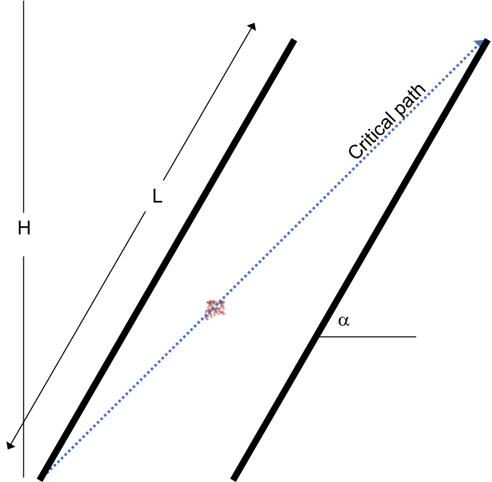
Fig. 160 Critical path between two plate settlers.
How far must the particle settle to reach the lower plate?
Let’s make a simplification and assume that water is flowing with uniform velocity between the plates, represented by a “top hat” velocity profile. This is a significant assumption, but it is used to help us understand the critical path. The fluid is carrying the floc between the inclined plates while gravity is pulling the floc down. Therefore, a particle must fall the vertical distance between the plates, which is the critical height, \(H_c\). The plates are positioned at an angle, \(\alpha\), to ensure that settling flocs slide down to the floc filter. The critical height \(H_c\) can be expressed in terms of plate settler length, \(L\), and plate settler angle, \(\alpha\), by \(H_c=\frac{S}{cos\alpha}\).
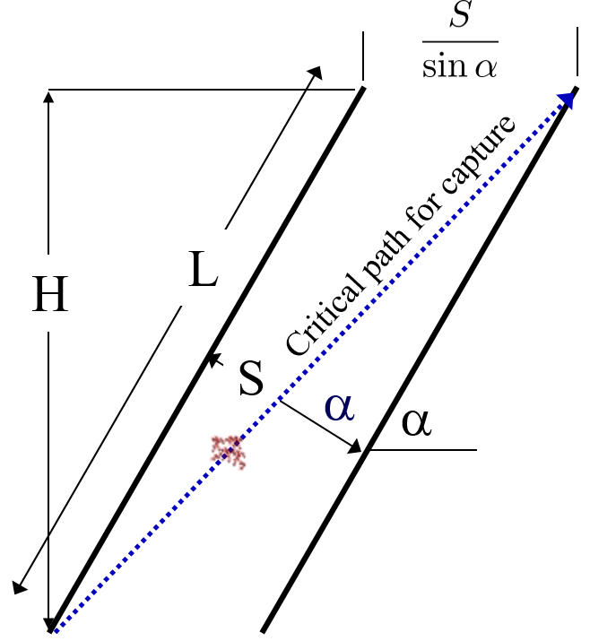
Fig. 161 Critical height between two plate settlers.
What is the total vertical distance that the critical particle will travel?
Taking the vertical component of the critical path, we see that the total vertical distance is \(H\) where \(H =L sin\alpha\).
What is the net vertical velocity of a floc between the plate settlers?
The fluid carries the floc between the plate settlers while gravity pulls the floc down. The velocity through the plate settlers has both a horizontal component, \(\bar v_{x_{Plate}}\), and vertical component, \(\bar v_{z_{Plate}}\), with a resultant velocity we call \(\bar v_{\alpha_{Plate}}\).
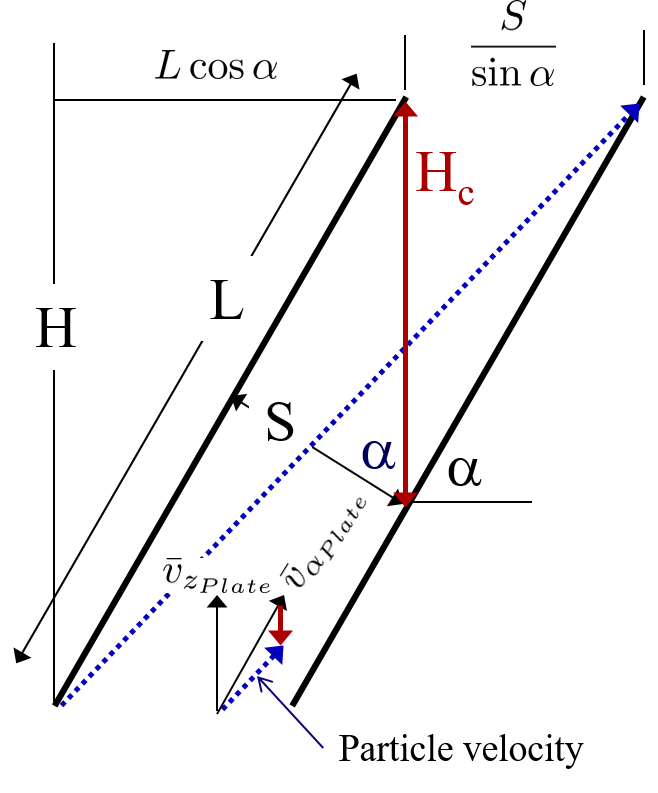
Fig. 162 Velocity components between two plate settlers.
This means that the net vertical velocity \(v_{z_{net}}\) is the vertical component of flow minus the settling velocity of the floc. Recall our previous discussion of terminal velocity and capture velocity; in this case, because we are designing a plate settler specifically to capture the critical particle, the terminal velocity equals the capture velocity. The terminal velocity is a function of the velocity that the critical particle settles at and the capture velocity is a function of the reactor geometry which we are designing to capture the critical particle. Thus, \(\bar v_{z_{net}} = \bar v_{z_{Plate}} - \bar v_{c}\).
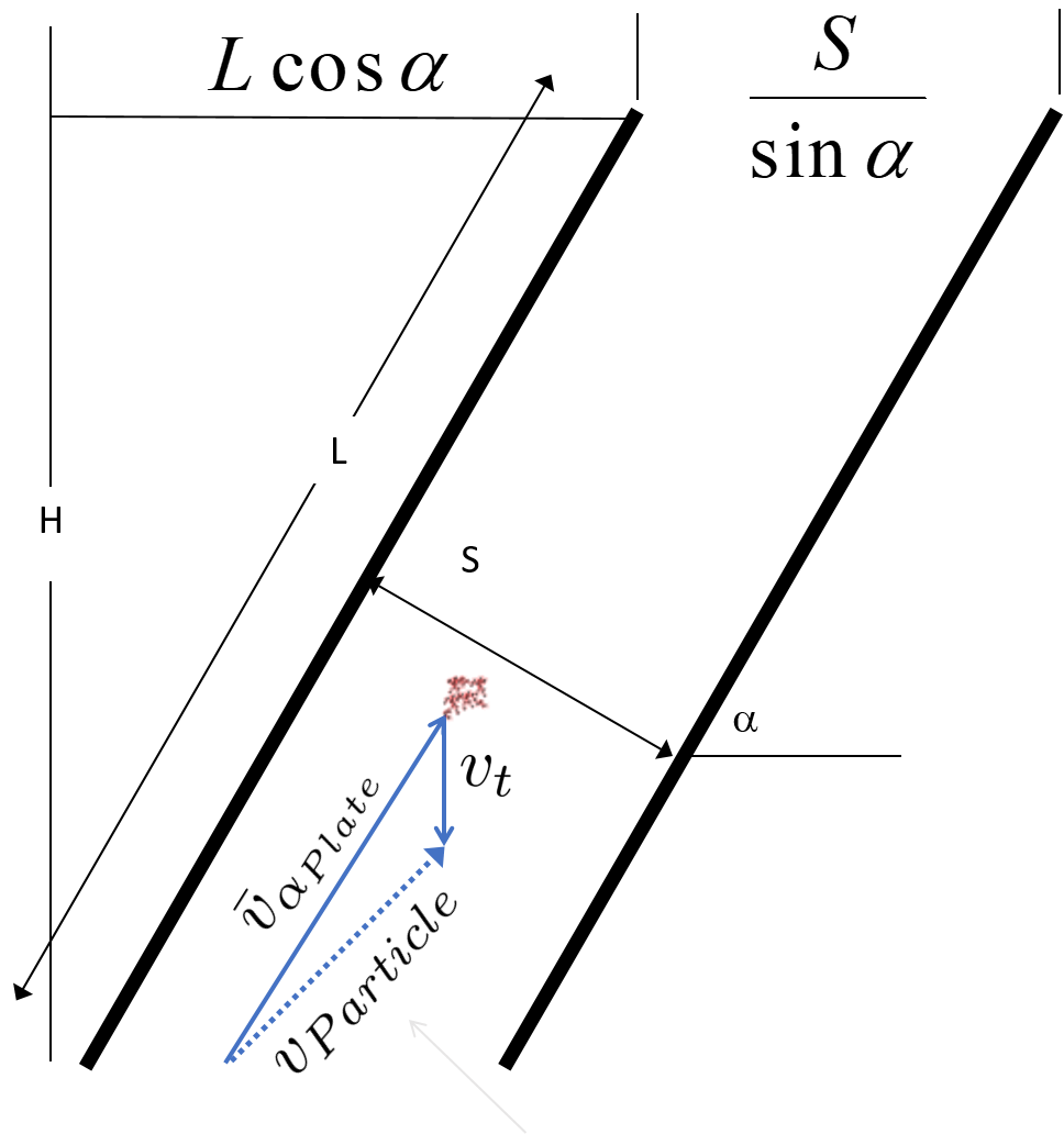
Fig. 163 Net velocity between two plate settlers.
From answering the questions above, we know that the particle must fall the distance \(H_c\) at its terminal velocity in the same amount of time that it rises a distance \(H\) at its net upward velocity, because otherwise it would not be captured; time to travel \(H_c\) = time to travel \(H\)
Finding time by dividing by distance by velocity for each travel,
Substituting for \(\bar v_{z_{net}} = \bar v_{z_{Plate}}-v_{c}\),
Using trigonometric substitutions for \(H_c\) and \(H\),
Rearranging to solve for \(\bar v_{c}\),
Rearranging to solve for \(\frac{\bar v_{z_{Plate}}}{\bar v_{c}}\),
The equation that we determined for capture velocity, \(\bar v_c\), shows its dependence on plate settler geometry. Through another derivation, we can prove that by considering the total projected area over which particles can settle, we determine the same capture velocity.
Beginning with \(Q = \bar vA\), we can modify the equation to fit the specific flow through a plate settler, \(Q = \bar v_{\alpha_{Plate}}SW\).
Using trigonometric substitutions, we know that \(\frac{\bar v_{z_{Plate}}}{\bar v_{\alpha_{Plate}}} = sin\alpha\) and \(\frac{\bar v_{z_{Plate}}}{sin\alpha} = v_{\alpha}\). So,
Determining the horizontal projection of the plate settlers,
Substituting for area, \(A\),
Solving for \(\bar v_c = \frac{Q}{A}\)
We can see that there are five parameters which will impact each other in our design \(\bar v_{z_{Plate}}, \bar v_{c}, L, S\), and \(\alpha\). AguaClara plants typically use constants for \(\bar v_{z_{Plate}}, \bar v_{c}, S\), and \(\alpha\), leaving \(L\) to be calculated. More information is found in the section on plate settler design.
The ‘active’ sedimentation zone refers to the area of the tank in which water can flow through the plate settlers where:
The only reason that there is a distinction between this area and the floc filter area is because plate settlers are built at an angle. This angle creates a “lost triangle” because there is a space in which the plate settlers are not effective and water does not flow through them. Because the active length is less than the floc filter length, \(L_{SedActive} < L_{SedFloc}\), and because flow must be conserved, the average active velocity must be greater than the average upflow velocity through the floc filter, \(\bar v_{z_{Active}} > \bar v_{z_{ff}}\). The same flow going through less area means that the velocity must increase.
Thus, \(Q_{Clarifier} = W_{Clarifier} L_{SedActive} \bar v_{z_{Active}}\), and \(\bar v_{z_{Active}} > \bar v_{z_{ff}}\).
Now, we will discuss flow through plate settlers where:
We know that plate settlers have a certain thickness and take up area, which means that once we reach the plate settler zone, there is less area for water to travel through. Because flow is conserved and there is a decrease in area, we know that the upflow velocity of water through the plate settlers must increase compared to the upflow velocity of water below the plate settlers, \(\bar v_{z_{Plate}} > \bar v_{z_{Active}}\).
Thus, \(\bar v_{z_{Plate}} > \bar v_{z_{Active}} > \bar v_{z_{ff}}\)
In addition to the vertical velocity component increasing between the plates, the resultant velocity of water between the plates increases compared to \(\bar v_{z_{Active}}\). What are the two reasons that this is true?
The first reason, as already discussed, is that the vertical velocity component needs to increase to ensure conservation of flow.
The second reason has to do with the fact that the resultant velocity of water between the plates is at an angle. This means that there is a horizontal component introduced. Because we know that the vertical velocity increases, and there is a new positive horizontal velocity component, the resultant velocity must also increase.
Now, consider a tube settler used in a lab setting instead of a plate settler. If a tube settler was designed with an angle to mimic a plate settler, would the water change vertical velocity after the angle? How does this compare to the plate settler scenario? In the case of the tube settler, the vertical velocity does not increase because there is no change in flow area; the diameter of the tube is constant throughout, meaning that for the flow to remain constant, the velocity does not change.
For another example of flow conservation, let’s consider the relationship between \(\bar v_{z_{Plate}} S\) and \(\bar v_{z_{Active}} B\). \(B\) is the center-to-center distance between plate settlers, and does not take into account the thickness of plate settlers. Considering only the center-to-center distance means that the area for water to travel through does to change from before the plate settlers to within the plate settlers because we are not accounting for any thickness. If the area does not change, then velocity should also not change to keep flow conserved. However, if we are to account for thickness, we must discuss \(S\) which is the spacing between plate settlers. This does take into account the change in area, which means that the velocity would need to increase through the lesser area. So if we look at the flow through plate settlers, we can confirm that \(\bar v_{z_{Plate}} S = \bar v_{z_{Active}} B\). By using flow conservation and plate settler geometry, we can begin to understand the mathematical relationships that drive design.
Now that we have established how flocs settle on the plate and the increase in plan view area that plate settlers offer, we need to discuss how flocs will act once they are on the plates. We want particles and flocs that settle to agglomerate and slide down the plate settlers to be returned to the floc filter. We will explore this concept by first considering the desired spacing between plate settlers.
Let’s start with a basic question. If we know that adding plate settlers improves performance, why don’t we just keep adding more and more plate settlers to our system? Is there any impact of placing plates closer together?
We know that more plates means more effective settling area which means that we could remover more particles and make our tank smaller to save money and limit the use of concrete. But how close can those plates be?
The Ten State Standards report that plate settlers should have a separation of two inches, with very long plate settlers, which means very deep tanks. Clarification tanks are usually 4 meters deep, maybe because filters are also deep. This is a result of the engineering context rather than the basic design principles. The Ten State Standards are primarily based off the modification of existing clarifiers which were usually built deep and then plate settlers were added. This means that there wasn’t added incentive to optimize the entire plate settler and tank process because the tanks were already built. However, AguaClara designs are made to use all of the AguaClara innovations in a green field, meaning that we are incentivized to optimize every part of this design process.
AguaClara plants can design for changes in the depth and/or plan view area of the tank for optimal plate settler efficiency. We want to have the smallest and shallowest tanks possible for low cost and ease of construction. We know that in the plate settler design, there is a dimensionless parameter of plate spacing to length, \(\frac{S}{L}\). The ratio is close to constant, which means that if we double the length of the plate settler, we can double the spacing between the plate settler and get the same performance as when we started. Conversely, if we halve the distance between the plate settlers, we can halve the length of the plate settlers. But how far can we push this? Can we make really compact plate settlers?
What we really want to know is: what is the connection between spacing of plate settlers and performance?
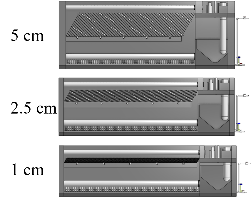
Fig. 164 Relationship between plate settler spacing and clarifier depth.
When we were discussed how plate settlers promote settling, we assumed a uniform velocity profile between the plates. However, we know from fluid mechanics and boundary layer rules that in reality, there is a nonuniform velocity profile. The flow between the plates, as determined by the Reynolds number, is laminar which means that there is a parabolic velocity profile between the plates and the shape of the parabola is affected by the distance between the plates.
Floc Rollup
There are some cases in which the plates are so close that even if flocs settle on the plate, they do not slide down. This is called floc rollup. Consider the following questions:
Why would flocs roll up?
It is a force balance! There is a force of gravity pulling the particle down, balanced with the force that the fluid flow exerts through drag related to viscosity. But why does it matter if plates are close together for floc roll up? The average velocity between plates is about 1 mm/s and is the same for any spacing. However, when plates are closer together the velocity profile is much steeper. Compared with plates with greater spacing, the closer plates cause there to be a higher velocity closer to the surface of the plate. This means that flocs between closely spaced plates will see a greater velocity closer to the plate settler, which will impact the force balance. The derivation of the force balance is found in the section on plate settler design.
How would you define the transition between floc rollup and slide down? What would describe the case for a floc that is stationary on the plate settler (not rolling up or sliding down?)
The transition is defined as when the gravitational forces and the fluid drag forces match.
Will little flocs or big flocs be most vulnerable to floc rollup?
This is a very complicated question. We would expect big flocs to slide down because they are heavier and have a greater gravitational force. However, bigger flocs also have a greater drag force and are out further into the flow. Because of the velocity profile, they will feel a higher velocity than smaller flocs. This means that the answer to this question should be determine mathematically, which it is in the next section.
Will large or small spacing between plates cause more floc rollup?
As we have already suggested, small spacing between plates will cause more floc rollup due to the steeper resulting velocity profile between the plates.
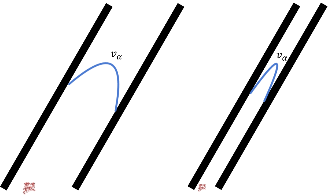
Fig. 165 Floc rollup between two plates (click to be sent to video).
So what does this mean for plate settler spacing? Let’s review some results from lab experiments. The following graph shows minimum plate settler spacing (mm) as a function of floc terminal velocity (mm/s). Some important things to note are that AguaClara plate settlers are designed for a capture velocity of 0.12 mm/s (recall that this capture velocity means that we want to capture flocs that are settling at 0.12 mm/s and faster). Before AguaClara filters were designed and deployed, AguaClara adopted the 0.12 mm/s capture velocity in an effort to reduce effluent turbidity as much as possible.
Why does the plate settling distance matter so much? How much does it impact the rest of the clarifier and its design?
One impact of plate settler spacing is on clarifier depth. We know that the spacing between plate settlers has a strong influence on clarifier depth and closer plate settlers allows for shallower tanks. There is a diminishing effect for small spacings, meaning that the difference in depth between 5 and 2.5 cm spacing is greater than the different in depth between 2.5 and 1 cm spacing. Because AguaClara does not yet have a good model for non-clay flocs, we cannot optimize our plate settler spacing and thus cannot optimize for the shallowest tanks possible.
Plate Settler Head Loss
Another impact of plate settler spacing is on flow distribution in the tank. This is related to our previous discussion of pressure recovery and flow distribution. Reduced spacing between plates leads to an increased pressure drop through the plate settlers due to higher head loss as shown in Equation (224). Therefore, plate settlers with small spacing will have more uniform flow distributions because head loss will dominate. This use of head loss can potentially get us better flow distribution. When the plates are brought closer together, there is more shear between the plates because the average velocity remains the same. The velocity gradient is higher between closer plates, which leads to higher shear, and thus higher head loss.
However, if the plates are closer together, then they will be shorter in length to keep the capture velocity constant. The decrease in length decreases the total amount of shear. The head loss from the competing impacts to shear can be determined through a force balance and the Navier-Stokes equation, as shown in the derivation of head loss through a plate settler.
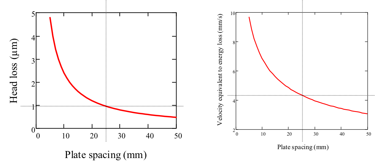
Fig. 166 Head loss as a function of plate settler spacing.
The important thing to note is that after determining head loss as a function of plate settler spacing, we realize that the plate settlers do not provide much head loss at the design separation of 2.5 cm. Head loss through plate settlers is really small, which means that they do not contribute much to equalizing flow distribution.
The velocities of any eddies or mean flow need to be less than 4 mm/s to achieve uniform flow through plate settlers. This means that if there is any flow entering the plate settlers at greater than 4 mm/s, the head loss provided by the plate settlers will not be sufficient to dampen the nonuniformity and there will not be adequate flow distribution. Luckily for us, the upflow velocity through the clarifier is on average 1 mm/s, which fulfills the requirement of less than 4 mm/s. The floc filter plays a very important role here in providing uniform vertical flow of 1 mm/s so that the flow between the plate settlers can be close to uniform.
References
Schulz, C. R., Okun, D. A., & Water and Sanitation for Health Project (U.S.). (1984). Surface water treatment for communities in developing countries. New York: Wiley.