Constant Head Tanks
Flow \(Q\) and Water Level \(h\) as a Function of Time
Our first step is to see if we can get constant head out of a simple system. The most simple flow control system is a bucket or tank with a hole in it. This system is too coarse to provide constant head. One step above that is a bucket or tank with a valve. This is where we begin our search for constant head.
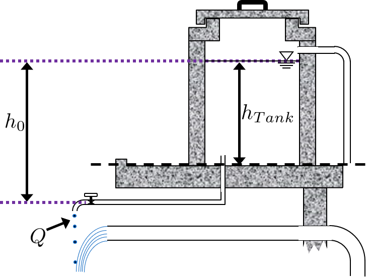
Using the setup described in the image below, we derive the following equation for flow \(Q\) through the valve as a function of time \(t\). The derivation is found here: Q(t) for a Tank with a Valve.

Fig. 56 This figure shows the variables that are defined in the equation above.
This equation has historically given students some trouble, and while its nuances are explained in the derivation, they will be quickly summarized here:
\(t_{Design}\) is NOT the time it takes to drain the tank. It is the time that it would take to drain the tank if the flow rate at time \(t = 0\), \(Q_0\), were the flow rate forever, which it is not. \(t_{Design}\) was used in the derivation to simplify the equation, which is why this potentially-confusing parameter exists. The actual time it takes to drain the tank lies somewhere between \(t_{Design}\) and \(2 \, t_{Design}\) and depends on the ratio \(\frac{h_{Tank}}{h_0}\).
\(h_{Tank}\) is not the same as \(h_{0}\). \(h_{Tank}\) is the height of water level in the tank with reference to the tank bottom. \(h_{0}\) is the water level in the tank with reference to the valve. Neither change with time, they both refer to the water level at one instance in time, \(t = 0\). Therefore, \(h_{0} \geq h_{Tank}\) is always true. If the tank is elevated far above the valve, then the \(h_{0} > > h_{Tank}\). If the valve is at the same elevation as the bottom of the tank, then \(h_{0} = h_{Tank}\). Please refer to the figure above to clarify \(h_{0}\) and \(h_{Tank}\).
We can use the proportionality \(Q \propto \sqrt{h}\), which applies to both minor losses and orifices to form a relationship between water level in the tank \(h\) and time \(t\). This proportionality comes from rearranging the minor loss Equation \(h = K \frac{Q^2}{2 g A^2}\) for \(Q\) instead of \(h\). A table of proportionality between \(Q\) and \(h\) can be found in Table 3
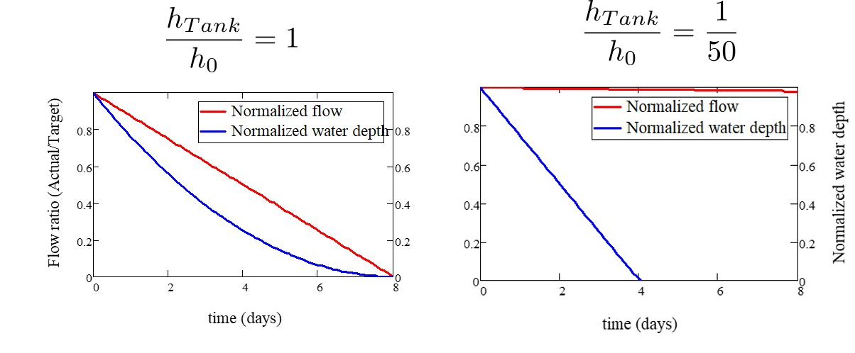
Using Equation (145) and this proportionality relationship, we make the following plots. On the left, the valve is at the same elevation as the bottom of the tank, or \(h_{Tank} = h_0\). Our attempt to get a continuous flow rate out of this system is to make \(\frac{h_{Tank}}{h_0}\) very small by elevating the tank far above the valve. On the right, \(\frac{h_{Tank}}{h_0} = \frac{1}{50}\). While the plot looks great and provides essentially constant head, elevating the tank by 50 times its height is not realistic. The ‘tank with a valve’ is not a solution to the constant head problem.

Fig. 57 These graphs show how manipulation of the variables in the \(Q(t)\) expression can result in effectively constant head.
Drain System for a Tank
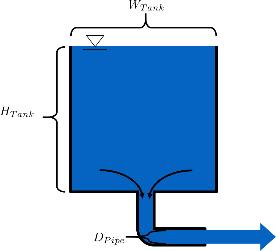
While the ‘tank with a valve’ scenario is not a good constant head solution, we can use our understanding of the system to properly design drain systems for AguaClara reactors like flocculators and clarifiers, since they are just tanks with valves. The derivation for the following equation is here, along with more details on AguaClara’s pipe stub method for draining tanks: D(t) and t(D) for Tank Drain Equation. The derived ‘Tank Drain’ equation is as follows:
The equation can also be rearranged to solve for the time it would take to drain a tank given its dimensions and a certain drain pipe size:

Fig. 58 Variables for draining a tank