Entrance Tank Design
Water treatment plants must be protected from potentially damaging materials that could be carried from the watershed to the plant by the water. There is typically a trash rack with large openings at the water source to prevent blockages and damage to the transmission line that conveys water to the plant. A small grit chamber may also be installed to remove sand and gravel before the water enters the transmission line. This equipment is only able to provide preliminary protection of the water treatment plant, and is generally insufficient for surface water sources. Excessive sand and gravel have historically caused maintenance challenges in some AguaClara plants by settling in the flocculator and the clarifier inlet channel. Source water from steep mountain streams often overwhelms the grit removal system during storm events with eroded sediment. Depending on the watershed characteristics, additional protection is often required to avoid failure modes downstream in the water treatment process.
The specific design characteristics of a water treatment plant dictate the potential failure modes and hence the required protection.
The entrance tank has multiple functions in a drinking water treatment plant.
Remove air bubbles to reduce splashing, turbulence, and unsteady motion of the chemical feed surface tracking lever system
Remove grit to prevent accumulation in the flocculator
Remove leaves and other debris to prevent clogging of the diffusers in the clarifier inlet
Dissipate kinetic energy to keep the water level steady for accurate flow measurement
Measure the incoming flow rate so that operators can make adjustments and respond to changes in water demand
Inject the coagulant and any other amendments required for flocculation
Water enters the entrance tank via the influent pipe and passes through the trash rack towards the Linear Flow Orifice Meter (LFOM). For water sources with large sediment loads, a grit chamber may be installed between the trash rack and LFOM to facilitate additional removal of sand and gravel. Plant operators can remove the pipe stubs blocking the drain on the bottom of each hopper, allowing water to pull settled grit into the waste channel below for disposal. An overflow pipe on the influent side of the trash rack prevents flows larger than the design flow rate from overwhelming the plant. The Chemical Dose Controller (CDC) lever arm and float sit between the trash rack and the LFOM and are used to dose the appropriate amount of chemicals into the plant as described previously in Chapter 6.
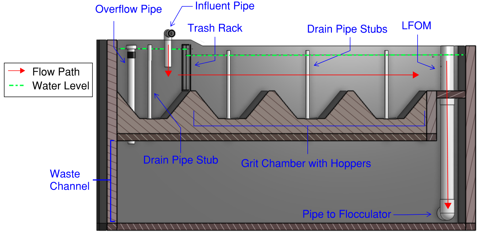
Fig. 73 Cross-section of an entrance tank. Lever arm of chemical dosing system not pictured.
In some AguaClara plants, the entrance tank, flocculators, and clarifiers are separated by walkways. However, a more space efficient approach would be to arrange the entrance tank in a channel next to the flocculator as constructed in the 120 L/s plant in Gracias, Honduras (Fig. 74). This avoids the need for buried pipes to carry water underneath the walkway from one component to the next and simplifies construction. In this layout, the entrance tank may extend up to the full length of the flocculator and then get wider as needed to meet grit removal requirements.
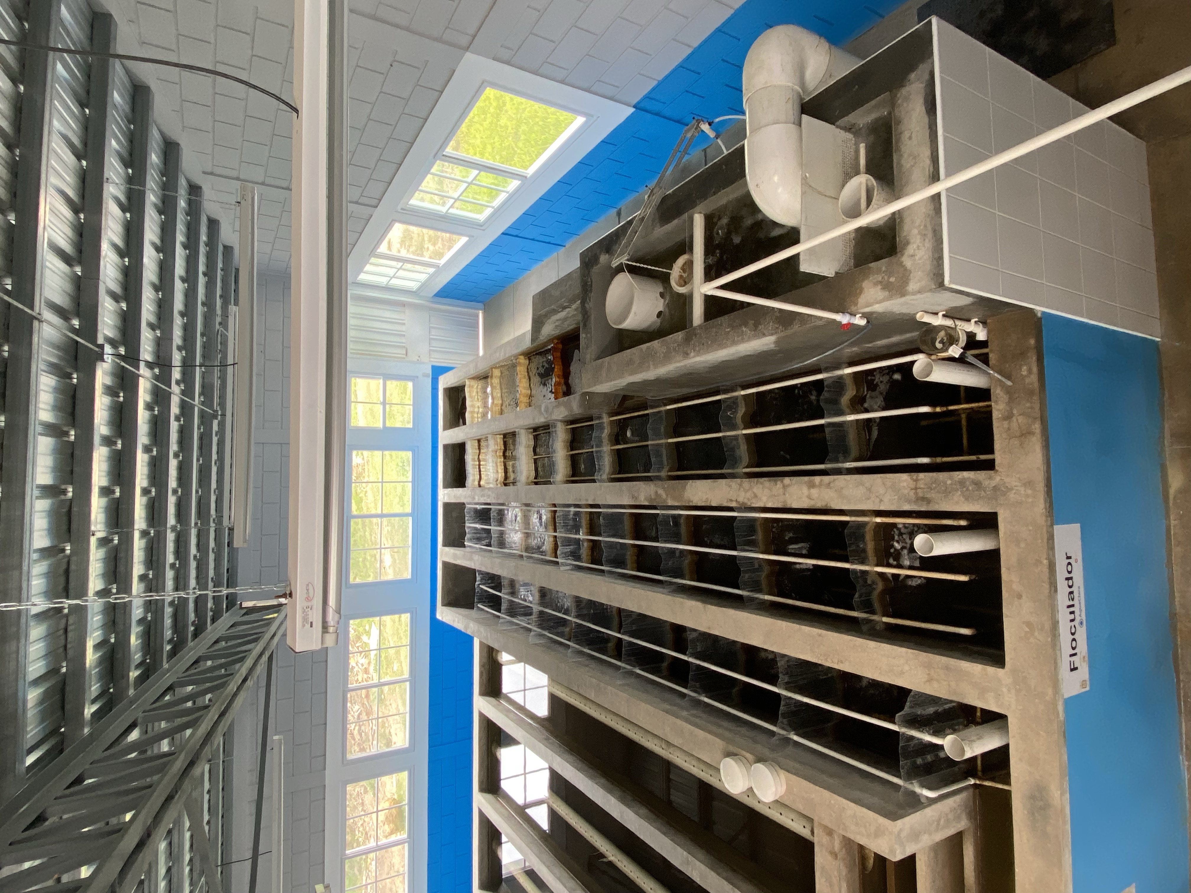
Fig. 74 A space efficient layout of the entrance tank alongside the flocculator in Gracias, Honduras.
Trash Rack Design
The trash rack is specifically designed to remove low density debris that could easily be carried through the plant and clog any small flow passages. In an AguaClara plant, there are critical flow passages in the clarifier inlet manifold diffusers and in the flow injection system in the stacked rapid sand filters. The inlet manifold diffusers have flared nozzles which currently have a minimum dimension of about 4 mm. The opening dimension for the trash rack must therefore be less than the opening size of the inlet manifold nozzles.
The minimum trash rack area is set to minimize head loss through the plant while maintaining an overall trash rack size that is reasonably compact. We recommend that the trash rack be designed to reach a terminal head loss of 5 cm when it is 90% clogged. The guiding principle for the design is the orifice equation modified to incorporate the fraction of the the trash rack area that is actually available for water to flow through. This area is reduced by the porosity, vena contracta, and amount of debris.
where \(\phi_{trashrack}\) is the fraction of clean trash rack that is open, \(\Pi_{vc}\) is the vena contracta coefficient, and \(\Pi_{clogged}\) is the clogged fraction of the trash rack. The ideal trash rack has a high porosity and a large vena contracta coefficient. The vena contracta coefficient is set by the entrance geometry of the trash rack openings. If the entrance has a sharp edge, then the vena contract coefficient will have a value of approximately 0.62. If the entrance is rounded then the vena contracta could approach 1.0. Thus, it is more efficient for a trash rack to have rounded openings.
The area of the trash rack can be solved for as follows:
Set the fraction clogged to between 80 and 90%. The vena contracta coefficient is 0.62 for sharp edged orifices and could be 1 for round wire. Porosity varies widely depending on the fabrication method. For AguaClara plants, a maximum head loss of 5 cm is recommended.
Also of interest is the effective velocity taking into account the whole area of the trash rack.
The trash rack characteristic velocity is 50 mm/s for 50% porosity, 90% clogged, vena contracta of 1, and a maximum head loss of 5 cm.
Grit Chamber Design
The length of the entrance tank can be extended to function as additional grit removal capacity for watersheds where sediment has the potential to produce harmful amounts of sand and gravel during storm events. As of 2021, plant operators at two AguaClara plants, Gracias and Agalteca, have reported maintenance issues due to grit settling in the flocculator or inlet channel to the clarifiers. If a grit chamber is deemed necessary for a particular watershed, it would be located on the effluent side of the trash racks and is lined with a series of hoppers to facilitate cleaning. To remove settled grit from the entrance tank, the plant operator can remove the pipe stub blocking the drain at the bottom of each hopper, allowing grit to flow into the drain channel below.
Stokes’ Law can be used to calculate the grit chamber area required to remove particles of a desired size. Kawamura recommends a critical particle size of 0.1 mm (2000, p. 416). The overall strategy to determine appropriate dimensions of the entrance tank is as follows:
Use the appropriate Stokes’ Law for laminar or turbulent flow to determine the corresponding critical velocity of the particle.
Calculate the required plan-view area of the entrance tank
Determine the ideal length and width of the entrance tank
Calculate the required entrance tank depth
Recall that Stokes Law tells us the terminal velocity of a particle settling under laminar flow, and can be calculated as:
where d:sub:’p’ is the minimum particle diameter to be removed (Kawamura recommends 0.1 mm).
As a check, calculate the Reynolds number to confirm that flow is in the laminar regime for Stokes’ Law to be valid.
The required plan view area to capture the minimum particle can be calculated by dividing the plant flow rate by the critical particle velocity:
The next step is to determine the optimal dimensions of the entrance tank. For constructibility purposes, the entrance tank must not be smaller than 50 cm, as a mason needs to work inside to apply a waterproof coating. Additionally, the entrance tank should not be longer than the flocculator. The ideal width of the entrance tank would be the area of the grit chamber divided by the length of the flocculator, or the minimum width of 50 cm, whichever is larger.
The corresponding entrance tank length would be:
The maximum height of water in the entrance tank is governed by either the trash rack or the head loss of the LFOM, and depends on the design flow rate of the plant. The minimum depth of the trash rack is its active area divided by the width of the entrance tank, and the LFOM head loss for a typical AguaClara plant is 20 cm.
The depth of the entrance tank is therefore the maximum of the trashrack depth and the LFOM headloss, plus some freeboard (typically 10 cm for AguaClara).
References
Kawamura, S. (2000). Integrated Design and Operation of Water Treatment Facilities. John Wiley & Sons.